It is a calibration bench for gas detectors.
It is a calibration bench for gas detectors.
The calibration bench for gas detectors allows the verification of the calibration of several gas detectors at the same time for the same mixture. A system of solenoid valves allows the selected gas to be conveyed from the cylinder to the detectors along a pneumatic path where are inserted the Mass Flow Controllers for the composition of the mixture, a device for air humidification, the pressure and temperature sensors for the control of these parameters during the test, the Flowmeters for the partialization of the flow rates between the detectors at the outlet.
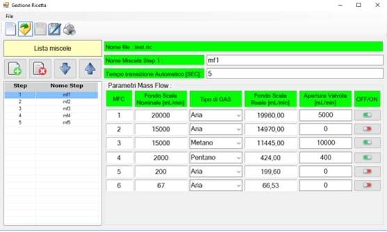
The test system is managed by a control unit and a computer. Mixes can be created on the computer and stored for immediate use during testing. The mixes can also be programmed to be produced in a sequence of stimulations for the detectors under test.
The control unit is the interface for the command and control of the electronic devices of the bench and can also be used to build and control tests in the event of a computer failure, although at the cost of less versatility of the interface with the operator.
The operator can check the programming step-by-step through the PC monitor or the control unit display. A separate monitor, called synoptic, displays the status of the bench in real time in the testing process.
Two proprietary software contained in the control unit and in the PC are intercommunicating with each other and manage the functions of the bench and the interface to the operator.
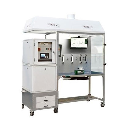
The bench, equipped with 6 pivoting wheels, is built in aluminum profile with a square profile while the work area is covered with a PVC plate. Next to the structure there are two cabins one above the other containing respectively the gas components and the electrical-electronic components. An “alucobond” plate (aluminum-polyethylene-aluminum) is inserted on the front of the worktop to contain the various components for calibrating the instruments.
Above the structure there is a hood, 2000 x 800, to convey the fumes that will be expelled through an aspirator. A Synoptic and a PC are installed in the calibration area.
The Synoptic is a 24” monitor used to view the process in progress.
The PC, with 17” Touch Screen, is used to set the calibration data.
On the worktop there is a container for the voltage sockets used by the equipment to be calibrated (while another is placed inside the electrical cabin), two push-button panels to manually control the solenoid valves for conveying gas to the instruments being calibrated and an Emergency push button. The work area is illuminated with a LED lamp.
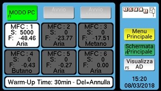
A working screen on the control unit